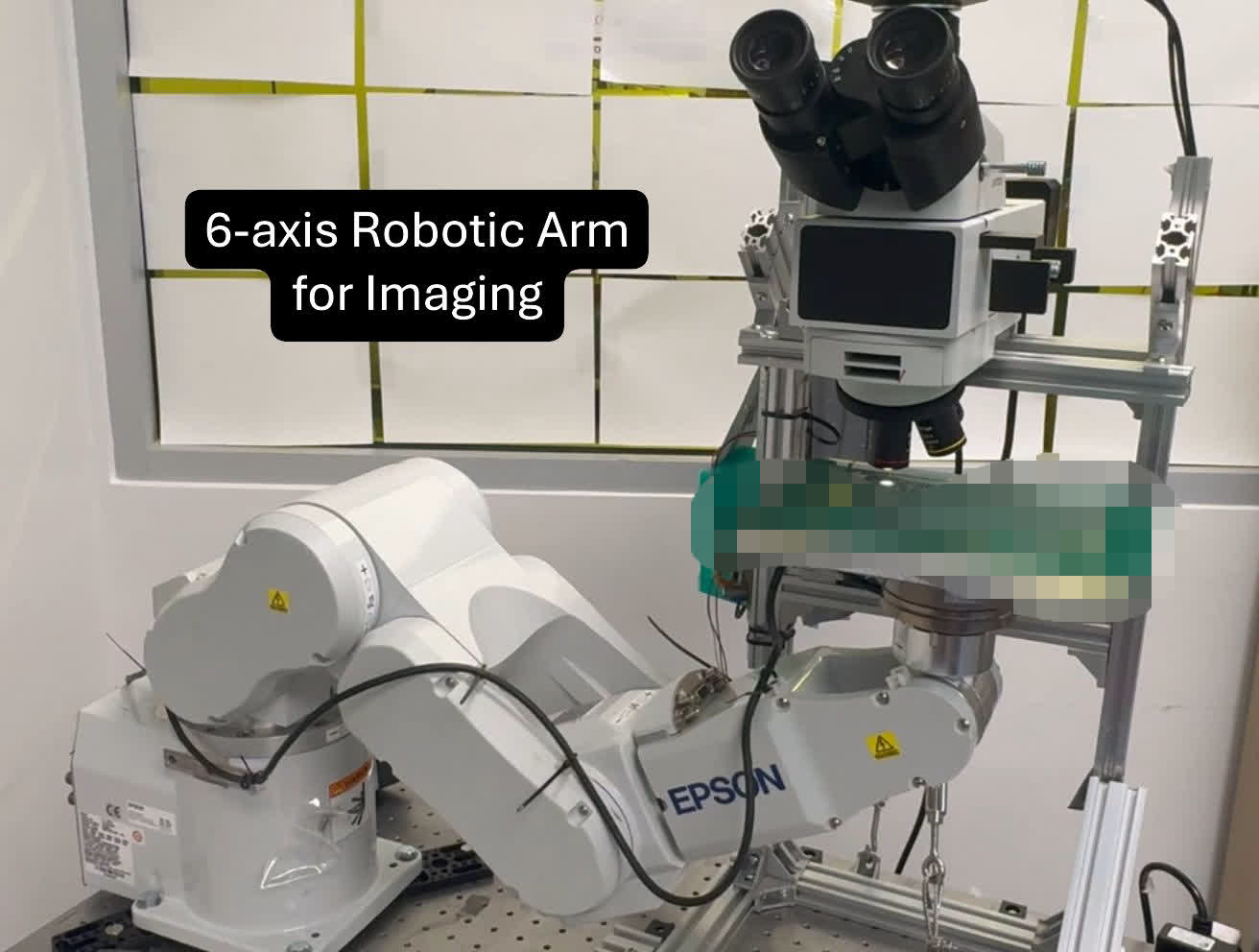
machine-vision inspection of sensor chips
- Alignment
- OpenCV detects chip centers in camera images. The software converts pixel offsets to microns and sends position corrections to the robot.
- Focus
- Three-stage focus search with commanded Z steps down to 0.001 mm. Focus stacking combines sharp regions from images taken at different heights.
- Scanning
- Serpentine scanning of a 7×5 chip grid, with board geometry loaded from teach-point files. Saved progress allows interrupted scans to resume at the sensor where they stopped.
- Operator interface
- Python server and web interface for monitoring scans, processing images, and reviewing results.
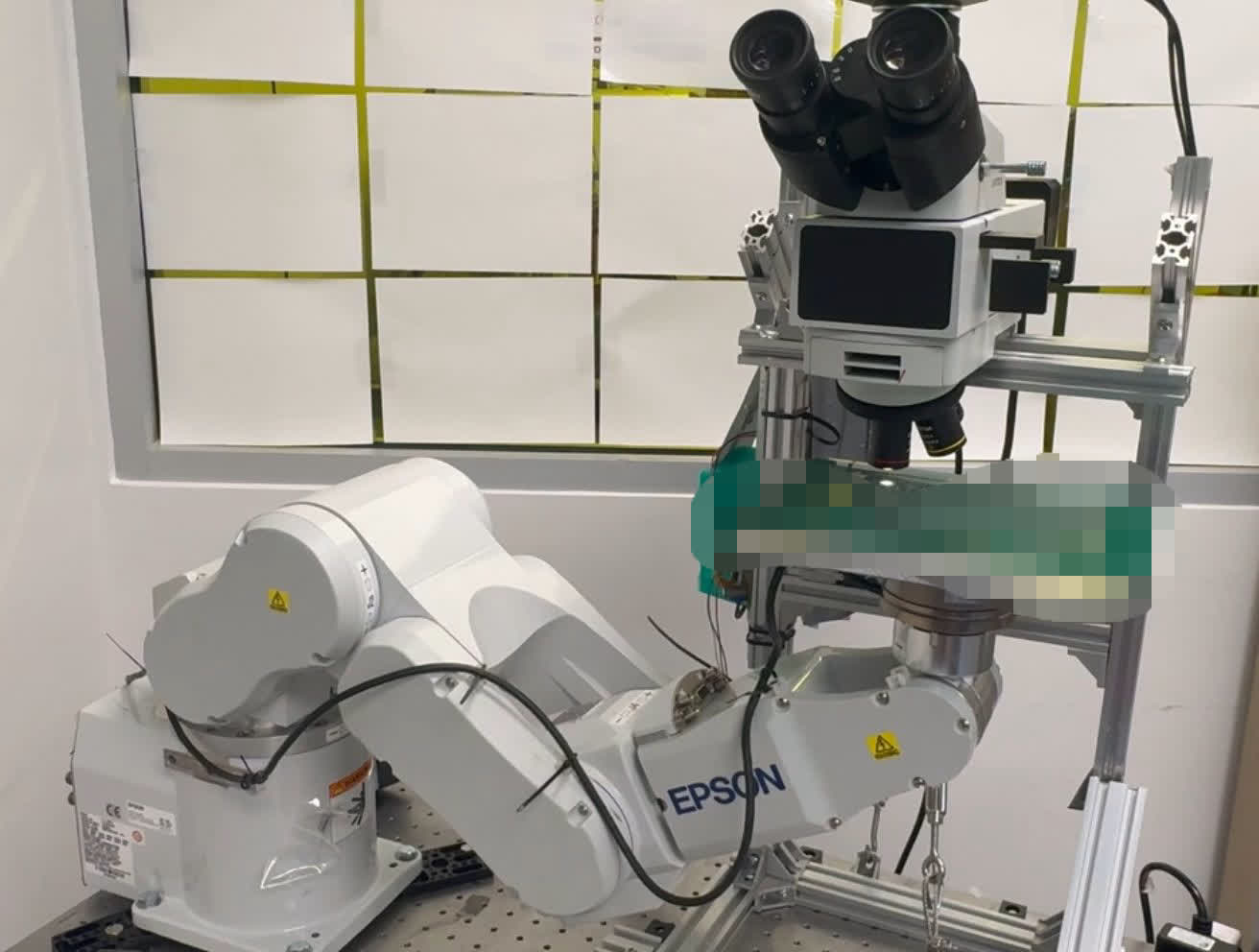
Inspecting every chip on a board previously required a technician to move it by hand under a microscope. This station automates positioning and focus, then saves the images for review in a browser.
I wrote the Epson robot program, Python vision server, and web interface.
Board alignment
Boards can sit slightly differently in the fixture, and their surfaces are not always flat. Before scanning, the robot captures images at reference corners of the fixture. OpenCV locates the chip center in each image.
The software converts the measured pixel offsets to microns, then maps them to the robot’s coordinate system. The camera and robot use different axis directions, so the conversion swaps and inverts the axes:
um_offset_x = pixel_offset_x * self.um_per_pixel
robot_x_offset = -um_offset_y   # image Y becomes Robot X, inverted
robot_y_offset = -um_offset_x   # image X becomes Robot Y, inverted
Three reference points determine the board’s position and rotation. The alignment module sends the corrections to the running robot program as SPEL+ commands.
Focus selection
At this magnification, the depth of field is measured in microns. The robot searches for focus in three stages: a coarse search, a fine search around the best position, and a final search with commanded Z steps of 0.001 mm.
' Configure focus finding parameters
FOCUS_Z_RANGE = 2.0      ' Search +/- 1mm from current Z (coarse)
FOCUS_Z_STEP = 0.2       ' 0.2mm steps for coarse focus search
FOCUS_FINE_RANGE = 0.1   ' Search +/- 0.1mm around coarse optimum
FOCUS_FINE_STEP = 0.01   ' 0.01mm steps for fine focus search
FOCUS_ULTRA_RANGE = 0.01 ' Search +/- 0.01mm around fine optimum
FOCUS_ULTRA_STEP = 0.001 ' 0.001mm steps for ultra-fine focus search
A single image may not keep the whole chip in focus. The station therefore captures several images at slightly different heights for each sensor. It can select the sharpest image or combine the sharp regions from multiple images.
For the combined image, the software calculates a Laplacian-variance focus map for each frame. It then selects each output pixel from the frame with the highest focus score at that position.
Scan path and recovery
The robot follows a serpentine path across the 7×5 chip grid. Teach-point files define the geometry for supported board types, including 24-plex boards with and without frames, and FAST plates.
The Python server saves each sensor’s scan status. After an interruption, such as an emergency stop or power loss, the scan can resume at the sensor where it stopped.
Each completed scan produces a set of chip images for the board. Scan parameters can be adjusted for different board sizes, so plates from the assembly station can be inspected using the same scan mode as bare chips.